


Acronym
Title
Brand
Title
Brand
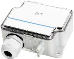
DPT-MOD (-IN)
Differential Pressure Transmitter with MODBUS Interface - Optional Input module


DESCRIPTION
DPT-MOD (-IN)
Differential Pressure Transmitter with MODBUS Interface - Optional Input module
Applications
The DPT-MOD differential pressure transmitter for air is designed to Modbus communication network (RTU).The digital signal can be sent as an output over Modbus communication network.
Usage & Applications
The Modbus transmitter can be used in all the in the same applications as the standard transmitters.Reduce costs
Reduce the installation costs and costs of wiring work with new Modbus transmitters. Modbus transmitters can do with much less wiring than the traditional 3-wire transmitters, since one or several Modbus devices can be connected on a serial line.Each device is individually temperature compensated.
Model summary
| Type name* | Accuracy for pressure** | Long term stability*** |
|---|---|---|
| DPT-MOD-2000 (-IN, -AZ) |
±1,5% or (±6Pa <250 Pa) from range |
≤ ± 8 Pa (with AZ ≤ ± 1 Pa) |
| DPT-MOD-5000 (-IN, -AZ) |
±1,5% from range | ≤ ± 24 Pa (with AZ ≤ ± 1 Pa) |
* -IN for Input module, -AZ for autozero
** -10 ÷ +50 °C
*** typical 1 year
Modbus address
1...247 Selectable by jumper and push button. Please see the chapter installation.Optional input module
Input module is fixed assembled expansion board for external signal conversion into modbus.Technical data: see the chapter II-module.
Modbus input module can be assembled afterwards.
(Compatible with DPT MOD version REV05 or later)
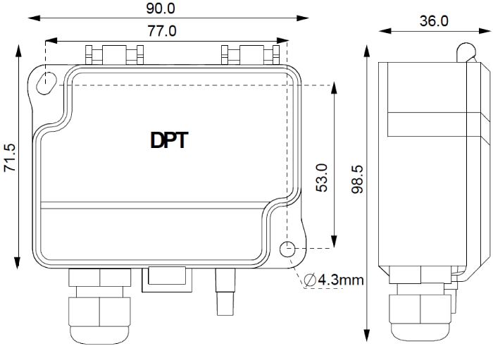
DIMENSIONS
Width [mm]
Height [mm]
Depth [mm]
Weight [g]
Outline drawings [mm]
Height [mm]
Depth [mm]
Weight [g]
Outline drawings [mm]
90,0
71,5
36,0
150 grams, with accessories 290 grams
71,5
36,0
150 grams, with accessories 290 grams
TECHNICAL DATA
Communication
Response Time
Zeroing function
Bursting pressure
Suitable media
Measuring Element
Electrical interface
Supply voltage
Power consumption
Output signal
Materials
Housing
Cover
Pressure connections
Connections
Pressure connections
Cable entry
General ambient conditions
Temperature range Operation
Storage
Ambient humidity
Safety
Protection standard
Conformance
MODBUS RTU, over RS485
8 data bits, parity bit: selectable, 1 stop bit, baud rate: selectable
0.8s / 2s / 10s
Access via MODBUS or by push button. Recommended every 12 months. or by optional autozero module. AZ calibrates zero point automatically. *)
30 kPa
Air and non-aggressive gases
Piezoresistive
24 VDC ± 10 % / 24 VAC ± 10 %
< 1.3 W
via Modbus
ABS
PC
ABS
Male ∅ 5,0 mm and 6,3 mm
M20
-10 ± +50°C
(setting display: 0°C ± +50°C)
(AZ model: -5 ± +50°C)
-20 ± +70°C
0 ± 95% RH
IP54
Meets the requirements for CE marking:
RoHS Directive: 2002/95/EC
EMC Directive: 2004/108/EC
WEEE Directive: 2002/96/EC
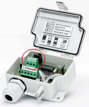
INSTALLATION
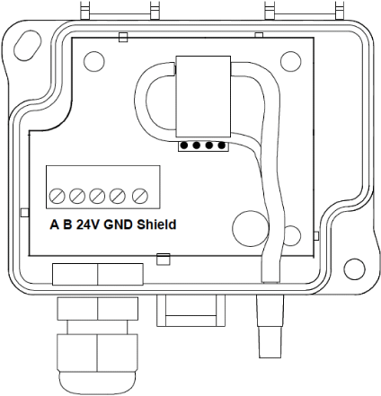
Connection Diagram
Settings
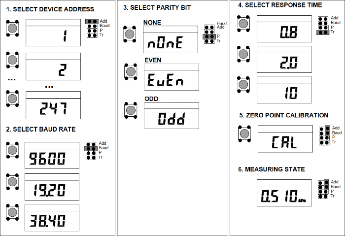
Zero-point adjustment
Note! Supply voltage must be connected one hour before the 0-point adjustment is carried out.1) Loose both tubes from the pressure inlets + and – or ensure that the existing differential pressure is zero. (eg. air handling unit switched off)
2) Send the zeroing command via modbus or press the push button. The red led turns ON.
3) Wait until LED turns off and then install tubes again to the pressure inlets
It is recommended to adjust the zero point every 12 months during normal operation
• If the transmitter is equipped with automatic zero element the manual zeroing is not required.
• If the differential pressure in the measurement point is controlled to be zero (etc. air handling unit switched off), the zeroing can be done via modbus.
Optional auto zero element *
Optional auto zero element makes the transmitter maintenance free for periodical manual zeroing. The element automatically adjusts the transmitters zero point from time to time, this eliminates the zero point long term drift of the piezoresistive sensing element.Zero point adjustment is carried out every 10 minutes. During zero point adjustment the output and display values will freeze to the latest measured value. The automatic zero point adjustment takes 3,5 seconds.
Modbus functions
The device supports to the following functions and registers:FUNCTION 04 - Read input Register
| Register | Parameter Description | Data type | Value | Range |
|---|---|---|---|---|
| 3x0001 | Program version | 16 bit | 0 ÷ 1000 | 0,00 ÷ 99,00 |
| 3x0002 | Pressure in Pascals | 16 bit | 0 ÷ 2000 | 0,00 ÷ 2000(Pa) |
FUNCTION 05 - Write Single coil
| Register | Parameter Description | Data type | Value | Range |
|---|---|---|---|---|
| 0x0001 | Zeroing function | 0 bit | 0 ÷ 1 | On - Off |
DESCRIPTION (Input Modules - IN)
(-IN)
Input Modules for Differential Pressure Transmitters
Input module is a plug-in module for DPT-MOD that converts external field signals into Modbus RTU network. It can be assembled into DPT-MOD afterwards, even in the field and on site.Usage & Applications
Enhanced with input module, the Differential Pressure Transmitter with Modbus interface can be used as a Temperature Transmitter as well.Reduce costs
Installation costs are significantly reduced when you do not need to use separate temperature transmitters or Modbus converters. Simply connect the temperature sensors into the input module and read the signal over Modbus RTU interface.Input signals can be read over MODBUS via DPT MOD RS484 interface.
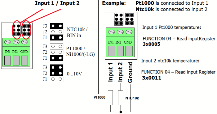
| Input | Signals | Accuracy for measurement |
Resolution (Modbus signal) |
|---|---|---|---|
| Input 1 and 2 | 0 ÷ 10V | < 0,5 | 0,1 % |
| ntc10k | < 0,5 | 0,1 % | |
| Pt1000 | < 0,5 | 0,1 % | |
| Ni1000/(-LG) | < 0,5 | 0,1 % | |
| BIN IN (potential free contact) |
Modbus functions and registers
FUNCTION 02 – Read Input status
| Register | Parameter Description | Data type | Value | Range |
|---|---|---|---|---|
| 1x0001 | Input 1 BIN IN | 0 Bit | 0 ÷ 1 | On - Off |
| 1x0002 | Input 2 BIN IN | 0 Bit | 0 ÷ 1 | On - Off |
FUNCTION 04 – Read input Register
| Register | Parameter Description | Data type | Value | Range |
|---|---|---|---|---|
| 3x0004 | Input 1 0 ÷ 10V | 16 Bit | 0 ÷ 100 | 0 ÷ 100% |
| 3x0005 | Input 1 Pt1000 temperature | 16 Bit | -500 ÷ 500 | -50 ÷ +50° |
| 3x0006 | Input 1 Ni1000 | 16 Bit | -500 ÷ 500 | -50 ÷ +50° |
| 3x0007 | Input 1 NTC10k | 16 Bit | -500 ÷ 500 | -50 ÷ +50° |
| 3x0008 | Input 2 0 ÷ 10V | 16 Bit | 0 ÷ 100 | 0 ÷ 100% |
| 3x0009 | Input 2 Pt1000 temperature | 16 Bit | -500 ÷ 500 | -50 ÷ +50° |
| 3x0010 | Input 2 Ni1000 | 16 Bit | -500 ÷ 500 | -50 ÷ +50° |
| 3x0011 | Input 2 NTC10k | 16 Bit | -500 ÷ 500 | -50 ÷ +50° |
| 3x0012 | Input 1 Ni1000-LG | 16 Bit | -500 ÷ 500 | -50 ÷ +50° |
| 3x0013 | Input 2 Ni1000-LG | 16 Bit | -500 ÷ 500 | -50 ÷ +50° |
Configuration
The jumpers should be set according to the instructions below and the value should be read from the right register. Both inputs can be configured independently.Jumpers
TECHNICAL DATA (INPUT MODULE -IN)
Communication
Electrical terminals
Number of input terminals
Electrical terminals
Number of input terminals
MODBUS RTU, over RS485
8 data bits, none parity, 1 stop bit, baud rate: selectable
3 x Screw terminal for wires, max 1.5 mm²
Push button for pressure zero point calibration
Cable entry M20
2 (both terminals can be used simultaneously and/or separately)
3 x Screw terminal for wires, max 1.5 mm²
Push button for pressure zero point calibration
Cable entry M20
2 (both terminals can be used simultaneously and/or separately)
AEROFILTRI s.r.l.Via Rubens, 23 • Milano • Italy