


Acronym
Title
Cod
Brand
Title
Cod
Brand
DPTL
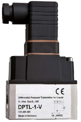
Differential Pressure Transmitter for Liquid DPTL


DESCRIPTION
DPTL
Differential Pressure Transmitter for Liquid DPTL
Applications
For differential pressure detection in liquid mediums of the air-conditioning, heating and water technique.Also suitable for light aggressive liquids.
Model summary
| Type code | Measuring range | Output signal | Accuracy typ. %/FS * |
|---|---|---|---|
| DPTL-1-V | 0 ÷ 1 bar | 0 ÷ 10 V | ±1 % |
| DPTL-1-A | 0 ÷ 1 bar | 4 ÷ 20 mA | ±1 % |
| DPTL-2,5-V | 0 ÷ 2,5 bar | 0 ÷ 10 V | ±1 % |
| DPTL-2,5-A | 0 ÷ 2,5 bar | 4 ÷ 20 mA | ±1 % |
| DPTL-4-V | 0 ÷ 4 bar | 0 ÷ 10 V | ±1 % |
| DPTL-4-A | 0 ÷ 4 bar | 4 ÷ 20 mA | ±1 % |
| DPTL-6-V | 0 ÷ 6 bar | 0 ÷ 10 V | ±1 % |
| DPTL-6-A | 0 ÷ 6 bar | 4 ÷ 20 mA | ±1 % |
- A for mA output
- V for voltage output
* (temperature: -20 ÷ 85°C)
DIMENSIONS
Width [mm]
Height [mm]
Depth [mm]
Packaging
Weight [g]
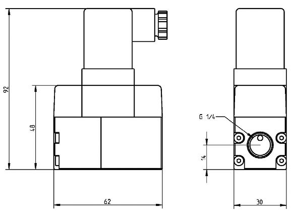
Outline drawings [mm]
Height [mm]
Depth [mm]
Packaging
Weight [g]
Outline drawings [mm]
510 g
TECHNICAL DATA
Materials
Material contacting the medium
Sealing material
Pressure
Static pressure maximum
Over pressure maximum
Responsetime
Connections
Electrical connector
Pressure connectors
Installation position
Enclosure
Bottom part
Top cover
Protection
Temperature
Ambient temperature
Temperature of medium
Storage temperature and moisture
Type DPTL xxx A
Supply voltage
Current consumption
Output signal
Type DPTL xxx V
Supply voltage
Power consumption
Output signal
Norms and standards
Product safety
EMC
CE-Conformity
Ceramic/Stainless steel A203/1 4305
EPDM
21 bar
6 bar, ranges 1 and 2,5 bar
16 bar, ranges 4 and 6 bar
10mS
Angle plug according to DIN 43650 Construction A
Inside thread G1/4"
Unrestricted
Stainless steel 1,4305
Aluminium pressure die casting
IP54 according to to EN60529
-10 ÷ 50 °C
-10 ÷ 80 °C
-20 ÷ 50 °C / max 85 %RH
15 ÷ 24 Vdc (±10 %)
max. 20 mA
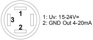
4 ÷ 20 mA, max load 900 ohm / 24 Vdc
15 ÷ 24 Vdc (±10 %) or 24 Vac (±10%)
typ. 0,37 W (Vdc) / 0,9 W (Vac)
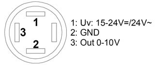
0 ÷ 10 V, min load 2 kOhm
EN61010-1 safety requirements for electrical equipment for measurement, control and laboratory use
EN61326-1 (2006) Electrical equipment for measurement, control and laboratory use EMC requirements
EN61326-2-3 Particular requirements- test configuration, operational conditions and performance criteria for transducer with integrated or remote signal conditioning
89/336/EEC Electromagnetic compatibility
INSTALLATION
CAUTION!
The modules must not be used in any relation with equipment that supports, directly or indirectly, human healt or life or with applications thet can result in danger for people, animals or real value.
• For connectingn the device, the process lines must be unpressurized.
• The device has to secured against pressure surges by appropriate measures.
• Note the suitability of the device for the medium to be measured.
• The device is designed for pipe mounting
• Note the maximum pressures
• To avoid the occurrence of interfering dead times, the pressure sensing leads shall be as small as possible and shall be layed witho0ut any sharp bends.
• With pulsating pressures on the system, function interferences of the device can be caused. As a protection , the installation of attenuaing element in the pressurized connection line is recommended.
Sensing devices with transducer should in principle be operated in the middle of the measuring range to avoid deviation at the measuring end points. the ambient temperature of the transducer electronics should be kept constant.
Before installing the device, the leak tightness of the pressurized connection lines must be inspected. +: Higher pressure -: Lower pessure
4 ÷ 20 mA Type
Security Advice
The installation and assembly of electrical equipment may only be performed by an authorized and skilled electrician.The modules must not be used in any relation with equipment that supports, directly or indirectly, human healt or life or with applications thet can result in danger for people, animals or real value.
Mounting Advices
• The device is desinged for assembly on smooth walls or mounting plates.• For connectingn the device, the process lines must be unpressurized.
• The device has to secured against pressure surges by appropriate measures.
• Note the suitability of the device for the medium to be measured.
• The device is designed for pipe mounting
• Note the maximum pressures
• To avoid the occurrence of interfering dead times, the pressure sensing leads shall be as small as possible and shall be layed witho0ut any sharp bends.
• With pulsating pressures on the system, function interferences of the device can be caused. As a protection , the installation of attenuaing element in the pressurized connection line is recommended.
Electrical connection
The devices are constructed for the operation of protective low voltage (SELV). For the electrical connection, the technical data of the corresponding device are valid.Sensing devices with transducer should in principle be operated in the middle of the measuring range to avoid deviation at the measuring end points. the ambient temperature of the transducer electronics should be kept constant.
Installation
A prerequisite for the operation I a proper installation of all elecrical supply, control and sensing leads as well as the pressurized connection line.Before installing the device, the leak tightness of the pressurized connection lines must be inspected. +: Higher pressure -: Lower pessure
Terminal connection
0 ÷ 10 V type4 ÷ 20 mA Type
AEROFILTRI s.r.l.Via Rubens, 23 • Milano • Italy