


Sigla
Titolo
Cod
Marchio
Titolo
Cod
Marchio
DPI
2 Relay Electronic Differential Pressure Switch


DESCRIPTION
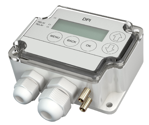
DPI
2 Relay Electronic Differential Pressure Switch
Each device has 4 selectable measuring ranges.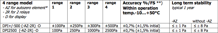
Each device is individually temperature compensated.
Models:
DPI+/-500 (-AZ-2R) -D
DPI2500 (-AZ-2R) -D
- 2R = 2 relays- D = display
- AZ = autozero element
*) -AZ model recommended when measuring pressures below 250 Pa.
**) %/FS from highest pressure range (including: general accuracy, temperature drift, linearity, hysteresis and repetition error).
Initial value is the factory calibration accuracy, better accuracy can be achieved with span point calibration.
The device has 0...10V output and 1 or 2 relay outputs (depending on the model).
The Differential Pressure Indicator is delivered individually packed with standard accessories (see accessories).
DIMENSIONS
Height [mm]
Width [mm]
Depth [mm]
Weight [kg]
Weight with accessories [kg]
Design Space [mm]
Width [mm]
Depth [mm]
Weight [kg]
Weight with accessories [kg]
Design Space [mm]
71,5
90,0
36,0
0,150
0,290
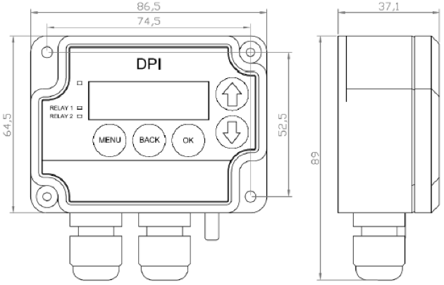
90,0
36,0
0,150
0,290
TECHNICAL DATA
Bursting pressure
Suitable media
Measuring element
Electrical interface
Supply voltage
with AZ option
Current consumption
Output signals, basic version
Output signals, 2R version
Materials
Housing, Pressure connections, Duct connectors
Cover
Tubing
Connections
Electrical connections
Power and 0...10V out
Relays 2 x SPDT
Cable entries
Pressure connections
General ambient condition
Temperature range Operation
Storage Ambient humidity
Safety
Protection standard
Conformance
30 kPa
Air and non-aggressive gases
Piezoresistive
21-35VDC/24VAC ± 10%
24VDC/VAC ± 10%
35mA + relays (7mA each) + AZ (20mA) + 0 ÷ 10V output (10mA)
Relay output (250VAC / 30VDC / 6A)
0 ÷ 10V, L min 1kΩ
Relay output 1 (250VAC / 30VDC / 6A)
Relay output 2 (250VAC / 30VDC / 6A)
0 ÷ 10V, L min 1kΩ
ABS
PC
PVC, soft
3 x screw terminals, max 1.5 mm2
6 x screw terminals, max 1.5 mm2
M16 and M20
Male ∅ 5,0 mm and 6,3 mm
-10 °C ÷ + 50 °C (-5 ÷ +50 °C for –AZ model)
-20 °C ÷ + 70 °C
0 ÷ + 95 % RH
IP54
Meets the requirements for CE marking:
EMC directive - 89/336/EEC
Rohs Directive - 2002/95/EY
ACCESSORIES
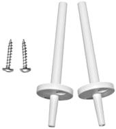
Standard accessories:
• 2 fixing screws
• 2 plastic duct connectors
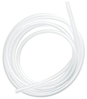
• 2m tube ∅4/7mm
Optionals
Metallic duct connector (to be ordered separately)
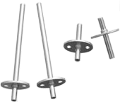
• 2 fixing screws
• 2 plastic duct connectors
• 2m tube ∅4/7mm
Optionals
Metallic duct connector (to be ordered separately)
INSTALLATION
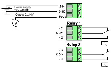
Notes when using high voltage for relays (115VAC ÷ 250VAC)!
The supply cable and control cable for relays should be separate if high voltage (115 ÷ 250VAC) is used in relay contacts. Both of the cables have their own cable entry.
Electrical connection diagram
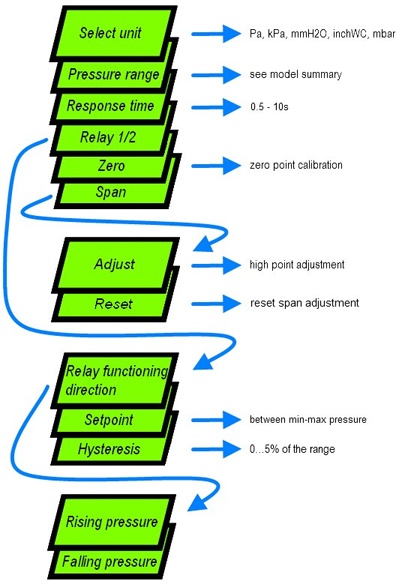
The settings are done according to the instructions below:
- with the MENU button you can enter the menu by pressing the button for 3 seconds, when in menu you can exit anywhere without making changes
- whit the BACK button you can return without making changes
- with the OK button you can open new options or confirm changes and return to previous display
- with the ↑↓ buttons you can scroll the menus
Zero point adjustment
Note!
Supply voltage must be connected one hour before the 0-point adjustment is carried out.
1) Disconnect both tubes from the pressure inlets + and –
2) Push both arrow buttons or select “Zero” from the menu > green led turns off and “Zero” text followed by a counter from 3 to 0 seconds is displayed
3) Attendere che il LED si spenga, quindi inserire nuovamente i tubi alle prese di pressione.
It is recommended to adjust the zero point every 12 months during normal operation.
* If the transmitter is equipped with automatic zero element the manual push button adjustment is not required.
Auto zero element *
Optional auto zero element makes the DPI maintenance free of periodical push button zeroing. The AZ element automatically adjusts the zero point of the transmitter from time to time; this eliminates the zero point long term drift of the piezo resistive sensing element.
Zero point adjustment takes about 4 seconds to perform and it is carried out every 10 minutes. Initially after power on, zero point is adjusted more often. After some time it is carried out every 10 minutes. During zero point adjustment the 0...10V output and relay outputs maintain their values and the display shows “zero” text.
If zero point is adjusted manually there is no need to disconnect the tubes when transmitter is equipped with the auto zero element.
High point adjustment (span)
Note!
Supply voltage should be connected one hour before the span point adjustment is carried out.
Note!
Span point must not be adjusted without input pressure. If the span point is adjusted with 0 Pa or close to 0 Pa input pressure the device may lose its accuracy and will not give out correct readings. In this case go to menu and select “Span” and then “Reset”. This resets the span adjustment.
To adjust the span you need an accurate reference meter.
Follow these steps to correctly adjust the span
1. Set the zero point *
2. Connect the input pressure
3. From the menu select “Span” and then “Adjust”
4. Adjust the display or 0 ÷ 10V value to match the reference meter’s value using the arrow buttons and confirm by pressing OK
*see section “Zero point adjustment”
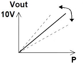
How span adjustment affects the measurement
The supply cable and control cable for relays should be separate if high voltage (115 ÷ 250VAC) is used in relay contacts. Both of the cables have their own cable entry.
Electrical connection diagram
The settings are done according to the instructions below:
- with the MENU button you can enter the menu by pressing the button for 3 seconds, when in menu you can exit anywhere without making changes
- whit the BACK button you can return without making changes
- with the OK button you can open new options or confirm changes and return to previous display
- with the ↑↓ buttons you can scroll the menus
Zero point adjustment
Note!
Supply voltage must be connected one hour before the 0-point adjustment is carried out.
1) Disconnect both tubes from the pressure inlets + and –
2) Push both arrow buttons or select “Zero” from the menu > green led turns off and “Zero” text followed by a counter from 3 to 0 seconds is displayed
3) Attendere che il LED si spenga, quindi inserire nuovamente i tubi alle prese di pressione.
It is recommended to adjust the zero point every 12 months during normal operation.
* If the transmitter is equipped with automatic zero element the manual push button adjustment is not required.
Auto zero element *
Optional auto zero element makes the DPI maintenance free of periodical push button zeroing. The AZ element automatically adjusts the zero point of the transmitter from time to time; this eliminates the zero point long term drift of the piezo resistive sensing element.
Zero point adjustment takes about 4 seconds to perform and it is carried out every 10 minutes. Initially after power on, zero point is adjusted more often. After some time it is carried out every 10 minutes. During zero point adjustment the 0...10V output and relay outputs maintain their values and the display shows “zero” text.
If zero point is adjusted manually there is no need to disconnect the tubes when transmitter is equipped with the auto zero element.
High point adjustment (span)
Note!
Supply voltage should be connected one hour before the span point adjustment is carried out.
Note!
Span point must not be adjusted without input pressure. If the span point is adjusted with 0 Pa or close to 0 Pa input pressure the device may lose its accuracy and will not give out correct readings. In this case go to menu and select “Span” and then “Reset”. This resets the span adjustment.
To adjust the span you need an accurate reference meter.
Follow these steps to correctly adjust the span
1. Set the zero point *
2. Connect the input pressure
3. From the menu select “Span” and then “Adjust”
4. Adjust the display or 0 ÷ 10V value to match the reference meter’s value using the arrow buttons and confirm by pressing OK
*see section “Zero point adjustment”
How span adjustment affects the measurement
AEROFILTRI s.r.l.Via Rubens, 23 • Milano • Italy